
9.4 M UPLINK FOR KDG
Kabel Deutschland (KDG), the largest system operator in Germany, operates the cable network in 13 states and supplies approximately 10 million subscribing TV households in Germany. The company operates the grids, markets cable connections and provides comprehensive services for the cable connection.
With the advent of digital TV, KDG decided to extend its offering with digital program packages in the broadband network. As a consequence, the company's existing monitoring concept and infrastructure had to be revised thoroughly. This revision coincided with the move to a new location, from Usingen to Roedelheim.
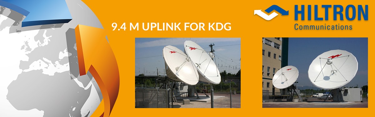
KDG selected Hiltron to build up the 9.4m Uplink in Frankfurt/Roedelheim.
Antenna Subsystem
- For nominal operation the 9,4 meter Ku-Band steerable motorized Transmit/Receive Earth Station Antenna. (type ANDREW ES94K-1) with a steptrack antenna control unit and the Hiltron outdoor motor control unit KDS is used
- Furthermore there is a 7,6 meter Ku-Band steerable motorized Transmit/Receive Earth Station Antenna. (type ANDREW ES76K-1) with antenna control and Hiltron Outdoor
- Motor Control Unit KDS. This antenna is the back-up for the 9,4 meter Ku-Band antenna.
- In case of a failure the switch-over to the redundant antenna is performed by the antenna back-up system ABUS.
Transmit Subsystem
- The transmit subsystem consists of (5 + 9) amplifier/upconverter chains. Each chain includes a 400 W Ku Band TWT Amplifier and an up-converter converting the IF of 70MHz to the Ku-Band. The chains are configured in 4:1 respectively 8:1 redundancy configuration.
- A fibre-optic system connects the uplink to the main building. Similar to the transmit chains the fibre-optic links are grouped in 4:1 respectively 8:1 redundancy configurations. The FO receivers and transmitters (type Foxcom 7830R7830T) are supplied and controlled by the Hiltron HCS3 FO Controller.
Receive Subsystem
- The subsystem is built up to a 1:1 redundant receive system.consisting of 2 dual ootput PLL LNBs, WG- / coax switches and power splitters.
- The received signals (L-band) are transferred to the main building by a L-band fibre-optic system. The link consists of 4 FO L-band FO transmitter and receiver supplied and controlled by the Hiltron HCS3 FO controller.
Monitoring and control
- Most of the equipment (Upconverters, HPAs, switches , LNBs, etc.) are controlled by the HILTRON HCS3 Controller. The HCS3 Controllers (in total 9) are configured according their application driving FO modules, switches, monitoring status messages etc.
- The HCS3 Controllers manage the automatic redundancy switching of equipment to guarantee the functionality even in the case when the Visionic M&C system is not operating.
- The monitoring & control system consist of a Visionic client server solution. The software includes the interface to the control software (RUP program) for the automatic redundancy switching and comprises the alarm & event management and logging and the logging of analogue parameters like beacon, azimuth level etc. All essential parameters and messages are summarized and indicated on a dedicated summary page on the GUI. The complete Visionic M&C system is manageable by SNMP and communicates to an overall KDG management system.
HILTRON GmbH | Emil-Rathenau-Str. 1 | D-71522 Backnang | Germany | T: +49-7191-343570 | Mail: info@hiltron.de IMPRINT
READ MORE HERE